Merchandise Description
SWC Collection-Medium-Obligation Designs Cardan shaft
Types
Knowledge and Measurements of SWC Sequence Universal Joint Couplings
| Sort | Design Data Product |
SWC160 | SWC180 | SWC200 | SWC225 | SWC250 | SWC265 | SWC285 | SWC315 | SWC350 | SWC390 | SWC440 | SWC490 | SWC550 | SWC620 |
| A | L | 740 | 800 | 900 | 1000 | 1060 | 1120 | 1270 | 1390 | 1520 | 1530 | 1690 | 1850 | 2060 | 2280 |
| LV | 100 | 100 | 120 | 140 | a hundred and forty | one hundred forty | one hundred forty | 140 | one hundred fifty | one hundred seventy | a hundred ninety | a hundred ninety | 240 | 250 | |
| M(kg) | 65 | 83 | 115 | 152 | 219 | 260 | 311 | 432 | 610 | 804 | 1122 | 1468 | 2154 | 2830 | |
| B | L | 480 | 530 | 590 | 640 | 730 | 790 | 840 | 930 | 100 | 1571 | 1130 | 1340 | 1400 | 1520 |
| M(kg) | 44 | sixty | 85 | 110 | 160 | one hundred eighty | 226 | 320 | 440 | 590 | 820 | 1090 | 1560 | 2100 | |
| C | L | 380 | 420 | 480 | 500 | 560 | 600 | 640 | 720 | 782 | 860 | 1040 | 1080 | 1220 | 1360 |
| M(kg) | 35 | forty eight | 66 | ninety | 130 | one hundred sixty | 189 | 270 | 355 | 510 | 780 | 970 | 1330 | 1865 | |
| D | L | 520 | 580 | 620 | 690 | 760 | 810 | 860 | 970 | 1030 | 1120 | 1230 | 1360 | 1550 | 1720 |
| M(kg) | 48 | 65 | 90 | one hundred twenty | 173 | 220 | 250 | 355 | 485 | 665 | 920 | 1240 | 1765 | 2390 | |
| E | L | 800 | 850 | 940 | 1050 | 1120 | 1180 | 1320 | 1440 | 1550 | 1710 | 1880 | 2050 | 2310 | 2540 |
| LV | 100 | one hundred | 120 | a hundred and forty | a hundred and forty | a hundred and forty | one hundred forty | a hundred and forty | a hundred and fifty | one hundred seventy | one hundred ninety | one hundred ninety | 240 | 250 | |
| M(kg) | 70 | 92 | 126 | 165 | 238 | 280 | 340 | 472 | 660 | 886 | 1230 | 1625 | 2368 | 3135 | |
| Tn(kN·m) | sixteen | 22.4 | 31.5 | 40 | sixty three | eighty | 90 | 125 | one hundred eighty | 250 | 355 | five hundred | 710 | a thousand | |
| TF(kN·m) | eight | eleven.two | 16 | 20 | 31.five | forty | 45 | sixty three | 90 | a hundred twenty five | one hundred eighty | 250 | 355 | five hundred | |
| Β(°) | 15 | fifteen | fifteen | fifteen | fifteen | 15 | fifteen | 15 | fifteen | 15 | fifteen | 15 | 15 | 15 | |
| D | one hundred sixty | a hundred and eighty | 200 | 225 | 250 | 265 | 285 | 315 | 350 | 390 | 440 | 490 | 550 | 620 | |
| Df | 160 | one hundred eighty | 200 | 225 | 250 | 265 | 285 | 315 | 350 | 3690 | 440 | 490 | 550 | 620 | |
| D1 | 137 | one hundred fifty five | one hundred seventy | 196 | 218 | 233 | 245 | 280 | 310 | 345 | 390 | 435 | 492 | 555 | |
| D2(H9) | a hundred | a hundred and five | one hundred twenty | a hundred thirty five | 150 | 160 | 170 | 185 | 210 | 235 | 255 | 275 | 320 | 380 | |
| D3 | 108 | 114 | a hundred and forty | 159 | 168 | a hundred and eighty | 194 | 219 | 245 | 273 | 299 | 325 | 402 | 426 | |
| Lm | ninety five | one hundred and five | a hundred and ten | a hundred twenty five | 140 | a hundred and fifty | one hundred sixty | 180 | 195 | 215 | 260 | 270 | 305 | 340 | |
| K | 16 | 17 | eighteen | 20 | twenty five | 25 | 27 | 32 | 35 | 40 | 42 | 47 | 50 | 55 | |
| T | four | 5 | five | five | 6 | 6 | 7 | eight | 8 | eight | 10 | twelve | twelve | twelve | |
| N | eight | eight | 8 | 8 | 8 | eight | eight | ten | ten | ten | 16 | 16 | 16 | sixteen | |
| D | 15 | 17 | 17 | 17 | 19 | 19 | 21 | 23 | 23 | twenty five | 28 | 31 | 31 | 38 | |
| B | 20 | 24 | 32 | 32 | 40 | forty | 40 | forty | fifty | 70 | eighty | 90 | one hundred | a hundred | |
| G | six. | 7. | nine. | nine. | twelve.five | twelve.5 | twelve.5 | fifteen. | sixteen. | 18. | 20. | 22.5 | 22.5 | twenty five | |
| MI(Kg) | two.fifty seven | three | three.85 | three.85 | five.seventeen | six | six.seventy five | 8.25 | ten.6 | thirteen | 18.50 | 23.75 | 29.12 | 38.08 | |
| Measurement | M14 | M16 | M16 | M16 | M18 | M18 | M20 | M22 | M22 | M24 | M27 | M30 | M30 | M36 | |
| Tightening torque(Nm) | 180 | 270 | 270 | 270 | 372 | 372 | 526 | 710 | 710 | 906 | 1340 | 1820 | 1820 | 3170 |
one. Notations:
L=Standard length, or compressed length for designs with length compensation
LV=Length compensation
M=Weight
Tn=Nominal torque(Yield torque 50% over Tn)
TF=Fatigue torque, I. E. Permissible torque as determined according to the fatigue strength
Under reversing loads
β=Maximum deflection angle
MI=weight per 100mm tube
2. Millimeters are used as measurement units except where noted
three. Please consult us for customizations regarding length, length compensation and
Flange connections.
(DIN or SAT etc. )
| Material: | Alloy Steel |
|---|---|
| Load: | Drive Shaft |
| Stiffness & Flexibility: | Stiffness / Rigid Axle |
| Journal Diameter Dimensional Accuracy: | IT6-IT9 |
| Axis Shape: | Straight Shaft |
| Shaft Shape: | Hollow Axis |
###
| Customization: |
Available
|
|---|
###
| Type | Design Data Item |
SWC160 | SWC180 | SWC200 | SWC225 | SWC250 | SWC265 | SWC285 | SWC315 | SWC350 | SWC390 | SWC440 | SWC490 | SWC550 | SWC620 |
| A | L | 740 | 800 | 900 | 1000 | 1060 | 1120 | 1270 | 1390 | 1520 | 1530 | 1690 | 1850 | 2060 | 2280 |
| LV | 100 | 100 | 120 | 140 | 140 | 140 | 140 | 140 | 150 | 170 | 190 | 190 | 240 | 250 | |
| M(kg) | 65 | 83 | 115 | 152 | 219 | 260 | 311 | 432 | 610 | 804 | 1122 | 1468 | 2154 | 2830 | |
| B | L | 480 | 530 | 590 | 640 | 730 | 790 | 840 | 930 | 100 | 1010 | 1130 | 1340 | 1400 | 1520 |
| M(kg) | 44 | 60 | 85 | 110 | 160 | 180 | 226 | 320 | 440 | 590 | 820 | 1090 | 1560 | 2100 | |
| C | L | 380 | 420 | 480 | 500 | 560 | 600 | 640 | 720 | 782 | 860 | 1040 | 1080 | 1220 | 1360 |
| M(kg) | 35 | 48 | 66 | 90 | 130 | 160 | 189 | 270 | 355 | 510 | 780 | 970 | 1330 | 1865 | |
| D | L | 520 | 580 | 620 | 690 | 760 | 810 | 860 | 970 | 1030 | 1120 | 1230 | 1360 | 1550 | 1720 |
| M(kg) | 48 | 65 | 90 | 120 | 173 | 220 | 250 | 355 | 485 | 665 | 920 | 1240 | 1765 | 2390 | |
| E | L | 800 | 850 | 940 | 1050 | 1120 | 1180 | 1320 | 1440 | 1550 | 1710 | 1880 | 2050 | 2310 | 2540 |
| LV | 100 | 100 | 120 | 140 | 140 | 140 | 140 | 140 | 150 | 170 | 190 | 190 | 240 | 250 | |
| M(kg) | 70 | 92 | 126 | 165 | 238 | 280 | 340 | 472 | 660 | 886 | 1230 | 1625 | 2368 | 3135 | |
| Tn(kN·m) | 16 | 22.4 | 31.5 | 40 | 63 | 80 | 90 | 125 | 180 | 250 | 355 | 500 | 710 | 1000 | |
| TF(kN·m) | 8 | 11.2 | 16 | 20 | 31.5 | 40 | 45 | 63 | 90 | 125 | 180 | 250 | 355 | 500 | |
| Β(°) | 15 | 15 | 15 | 15 | 15 | 15 | 15 | 15 | 15 | 15 | 15 | 15 | 15 | 15 | |
| D | 160 | 180 | 200 | 225 | 250 | 265 | 285 | 315 | 350 | 390 | 440 | 490 | 550 | 620 | |
| Df | 160 | 180 | 200 | 225 | 250 | 265 | 285 | 315 | 350 | 3690 | 440 | 490 | 550 | 620 | |
| D1 | 137 | 155 | 170 | 196 | 218 | 233 | 245 | 280 | 310 | 345 | 390 | 435 | 492 | 555 | |
| D2(H9) | 100 | 105 | 120 | 135 | 150 | 160 | 170 | 185 | 210 | 235 | 255 | 275 | 320 | 380 | |
| D3 | 108 | 114 | 140 | 159 | 168 | 180 | 194 | 219 | 245 | 273 | 299 | 325 | 402 | 426 | |
| Lm | 95 | 105 | 110 | 125 | 140 | 150 | 160 | 180 | 195 | 215 | 260 | 270 | 305 | 340 | |
| K | 16 | 17 | 18 | 20 | 25 | 25 | 27 | 32 | 35 | 40 | 42 | 47 | 50 | 55 | |
| T | 4 | 5 | 5 | 5 | 6 | 6 | 7 | 8 | 8 | 8 | 10 | 12 | 12 | 12 | |
| N | 8 | 8 | 8 | 8 | 8 | 8 | 8 | 10 | 10 | 10 | 16 | 16 | 16 | 16 | |
| D | 15 | 17 | 17 | 17 | 19 | 19 | 21 | 23 | 23 | 25 | 28 | 31 | 31 | 38 | |
| B | 20 | 24 | 32 | 32 | 40 | 40 | 40 | 40 | 50 | 70 | 80 | 90 | 100 | 100 | |
| G | 6.0 | 7.0 | 9.0 | 9.0 | 12.5 | 12.5 | 12.5 | 15.0 | 16.0 | 18.0 | 20.0 | 22.5 | 22.5 | 25 | |
| MI(Kg) | 2.57 | 3 | 3.85 | 3.85 | 5.17 | 6 | 6.75 | 8.25 | 10.6 | 13 | 18.50 | 23.75 | 29.12 | 38.08 | |
| Size | M14 | M16 | M16 | M16 | M18 | M18 | M20 | M22 | M22 | M24 | M27 | M30 | M30 | M36 | |
| Tightening torque(Nm) | 180 | 270 | 270 | 270 | 372 | 372 | 526 | 710 | 710 | 906 | 1340 | 1820 | 1820 | 3170 |
Choosing the Right PTO for Your Machine
There are many types of PTOs, and you may be wondering which one is the best choice for your machine. In this article, you’ll learn about Splined PTOs, Reverse PTOs, and Independent PTOs. Choosing the right PTO for your needs will allow you to operate your machine more efficiently.
LPTO
LPTOs can be dangerous for operators. They should stay at a safe distance from them to avoid getting entangled in the rotating shaft. If an operator gets caught, he or she could sustain severe injuries or even death. Safety precautions include wearing clothing that does not cling to the shaft.
There are many types of PTOs. Some of them support high power applications. These models have different shafts with varying spline configurations. Type 3 shafts have 20 splines, while Type 2 shafts have just 10. Type 3 and Type 2 shafts are referred to as large 1000 and small 1000 respectively by farmers.
The power that drives the PTO shaft comes from the gearbox through the countershaft. Standardizing the PTO speed helps to design equipment around the given speed. For example, a threshing machine is supposed to run at a specific peripheral velocity of the threshing cylinder, so pulley arrangements are usually designed with that speed in mind.
Because the PTO shaft is often low to the ground, it is easier to handle it from a kneeling position. Using a good surface to place the implement on will help you align the splines properly. To make this process easier, use a floor mat, a carpet, or a sturdy piece of cardboard. Once you have positioned the shaft on the PTO, press the locking pin button. If the PTO shaft is stuck, jiggling the implement a bit will help it slide into position.
Reverse PTO
There are several different ways to reverse the PTO shaft. Some older Massey Ferguson style tractors are designed to reverse the PTO shaft by turning it backward. This feature is useful for raising upright silo unloaders. The first method involves driving backward with the rear wheel jacked up and rotating while the rear wheel spins. This method is also useful for reversing a baler or unplugging a baler.
Another option is to install a reverse PTO adapter. These adapters are available for all types of PTOs. A reverse PTO is an excellent choice for any implement that can get stuck when rotating in one direction. However, it should only be used when it is absolutely necessary. The reverse PTO should not be rotated too far backward or for too long.
There are also different types of PTO shafts. Some transfer energy faster than others. That is why a large tractor’s PTO will transfer energy faster than a small tractor’s. Furthermore, independent PTOs don’t require a parking break like transmission PTOs do. There is also a difference between metric and domestic PTO shafts.
In farming, the reverse PTO is used when the farm machinery gets stuck or needs to be reversed. It also makes it possible to use the tractor to turn in the opposite direction. A PTO is a mechanical gearbox that transfers energy from the tractor’s engine to other implements. It can also supply power in the form of rotating pumps.
Splined PTO
The splined PTO shaft consists of six equal-sized splines that are spaced apart by grooves. The splines are angled to the axis of rotation of the PTO shaft. When the splines and the grooves meet, they align the screw end portion.
A splined PTO shaft can be retrofitted to most size 6 PTO shafts. It can also be used as a replacement for a worn out or damaged PTO shaft. This type of PTO shaft is recommended for tractors that require a quick and easy install.
Splined PTO shafts can be used for different types of agricultural equipment. They are compatible with standard and Weasler yokes. They can be cut to size and are available in North American and Metric series. They also come in an Italian Metric series. These shafts are easy to install and remove with a simple key.
A splined PTO shaft is essential for facilitating the interconnection of different components. A power take off (PTO) shaft tool engages the splined PTO shaft and turns it in order to align it with the input shaft of a cooperating structure. This tool is used to connect the PTO shaft to a tractor. This can also be used on a truck, trailer, or any other powered vehicle.
A wrench 40 is also useful for securing a PTO shaft. It enables the wrench to rotate the P.T.O. shaft approximately 30 degrees. The wrench’s leg 46 engages the shaft on the opposite side of the PTO shaft 16. Once the wrench is tightened, the tool can rotate the PTO shaft to make it align with the input shaft 16.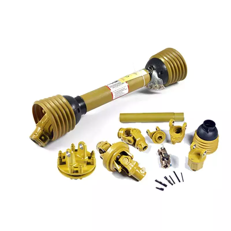
Independent PTO
Independent PTO shafts can be mechanical or hydraulic. The mechanical type has a separate on/off selector and control lever, whereas hydraulic PTOs have just one. The mechanical version is preferred for tractors that need to operate at lower speeds and for applications such as baling and tilling. The hydraulic version reduces noise and vibration.
Another advantage of an independent PTO is that it is easy to engage. Instead of engaging a clutch, you simply shift the PTO selector lever away from ‘OFF’ and flip the PTO switch to “ON.” This lever is usually located on the right hand side of the operator’s seat.
The ISO 500 standard provides specifications for independent PTO shafts. This specification lays out the size of the shaft, number of splines and the location of the PTO. In addition, it specifies the maximum RPM and shaft diameter for a PTO. The original ISO 500-3 specification calls for 540 revolutions per minute for shafts with six splines.
Another benefit of an independent PTO is its ability to be engaged or disengaged without using the transmission clutch. The lever can be pressed halfway or fully to engage an independent PTO. The independent PTO also allows you to stop the tractor while it is in motion. Independent PTOs are available in hydrostatic or mechanical configurations, and are particularly popular with hydrostatic drives.
LPTO shaft guard
An LPTO shaft guard prevents accidental rotational collisions by covering the shaft of a PTO. A PTO shaft is a moving part that can entrap a person’s legs, arms, and clothing. In a pinch, a person could become entangled in the shaft and suffer a serious injury. A PTO shaft guard is a great way to protect yourself against these dangerous incidents.
PTO mishaps can cause severe injuries and even fatalities. To prevent this, equipment manufacturers have made strides in improving the design and construction of their PTO drive shafts. A PTO shaft guard will protect the drive shaft from entanglement and tearing. Proper installation and maintenance of a PTO shaft guard can help protect the tractor, PTO, and other machinery.
Tractor PTO shaft guards are made from durable plastics and can be installed easily. They keep all the parts of the tractor in place and prevent accidents during operation. These parts are vital components for many farm equipments. A 540 RPM shaft can pull a person from a distance of five feet. A PTO shaft guard will prevent this from happening by keeping clothing from becoming entangled in the shaft.
Another important component of a PTO system is the master shield, which covers the PTO stub and the input driveline shaft of an implement. The master shield protects both the tractor PTO stub and the connection end of the input driveline shaft. It extends over the PTO stub on three sides. Many people never replace their master shields because they are too expensive.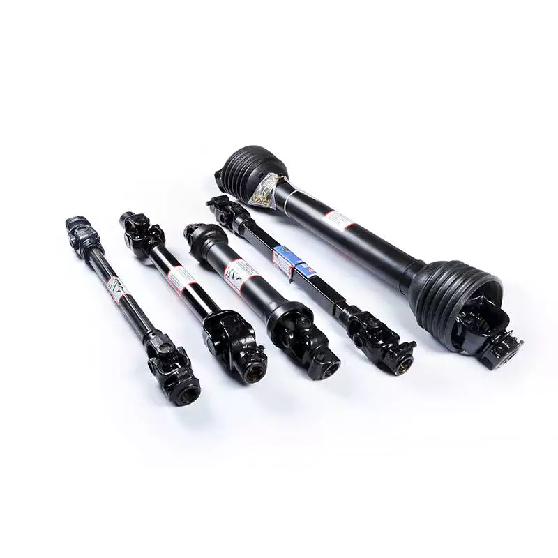
Safety of handling a pto shaft
Handling a PTO shaft safely is a vital component of tractor safety. Safety shields must be properly fastened to the shaft to prevent any accidents. The shield should also be inspected and maintained regularly. Otherwise, foreign materials, including clothing, can enter the shaft’s bearings. It is also important to walk around the rotating shaft whenever possible.
Power takeoff shafts are used to transfer mechanical power from farm tractors to implements. However, improper handling of these devices can lead to severe injuries, including amputation and multiple fractures. Spinal injuries are also common, especially if an individual is rotated around the shaft.
Operator awareness is key to avoiding PTO entanglement. Performing repairs while a machine is in operation or wearing loose, frayed clothing may lead to injury. It is also important to read the manufacturer’s instructions before operating a PTO. Lastly, it is important to never operate a PTO while the engine is running.
PTO shafts should be protected by ‘U’ or ‘O’ guards on the tractor and the attached implement. It is also important to use a PTO stand. As with any mechanical part, handling a PTO shaft requires care. Always ensure that the tractor is off before working and remove the key before working on it. Also, it is important to avoid stepping on the drive line or going under it. Make sure you wear protective clothing and shoes. Avoid wearing clothes that have laces as they could become entangled in the shaft and cause injury.
The connection to the PTO shaft should be close to the ground. If it is not, kneel on a flat surface. A piece of carpet, automobile floor-mat or cardboard can work well. Then, align the splines on the PTO shaft. To do this, press the locking pin button, then pull the ball-lock collar back, and then push the shaft onto the PTO.

editor by czh 2023-01-29